Connect TapNLink Primer to the target board’s SWD/JTAG port
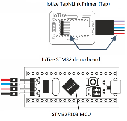
The four wires that need to be connected are:
- Red wire on VCC
- Blue wire on DIO
- Orange (or pink) wire on CLK
- Black wire to GND
The purple cable is the reset signal and it is not used by this demo. But it could be used to reset the target board.
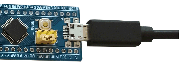
Once these wires are connected, you still have to supply a voltage of 5V to the boards. The easiest way is to connect a micro-USB cable between the BluePill board and a mobile charger (or the USB port of a computer).

💡 Note:
-
The Tap view corresponds to a 'bottom view' and the STM32 demo board corresponds to a 'top view'.
-
SWD is the default protocol, you can configure the Tap to use S3P (not recommended for a very first discovery). Note that S3P could use the exact same connection.