Controlling your TapBus system
A TapBus system can be controlled locally or remotely by a generic application (TapBus-Manager) provided by IoTize or by your own dedicated applications, generated from Iotize's App Creator and App Generator tools.
Accessing Slave Modules
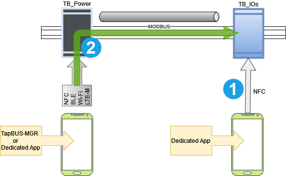
There are two ways to access a slave module:
-
Either directly via NFC. Direct access via NFC is only possible from a dedicated app. It should be noted that a mobile phone designed in NFC can eventually serve as a relay to another application.
-
Or via the system's gateway module (i.e. a TapBus-Power module). The TapBus-Power module acts as a 'master' to the bus and thus offers a single access to all modules. In this case, we can consider either local communication (via Wi-Fi, ethernet, BLE...) or remote communication (MQTT over Wi-Fi or LTE-M / NB-IoT).
The tools offered by Iotize make it possible to create a mobile application dedicated to the system in context. However, the generic TapBus Manager application is always available either for initial configuration or as a control interface when the system does not require a dedicated application.
TapBus Manager
This generic app (built entirely with App Creator) is available as a WebApp and mobile (iOS and Android). It allows you to control a TapBus system via the TapBus-Power module in order to:
-
Configure the various tasks (alarms, datalog, battery test,...),
-
Check the status of the battery and the system,
-
List slave modules, change their address and check their status, etc.
-
Configure slave module channels
-
Visualize the states of each channel of a slave module,
-
Display current alarms,
-
Configure the datalog,...
The following paragraphs detail these different features.
System Configuration
The system configuration is done via the 'Settings' tab (the last one on the right). The page contains a set of 4 groups (accordions):
-
General
-
Battery
-
Slave Modules
-
Datalog
We are first interested by the settings inside the General accordion. Several parameters can then be indicated:
Time Management
The period indicated is the period at which the TapBus-Power module will broadcast a time message to the slaves in order to resynchronize them. The default is 720 minutes, or 12 hours. The master itself will automatically resynchronize if it is connected to the internet (from the NTP server specified in its configuration), or from the mobile application when a (duly authorized) user logs in.
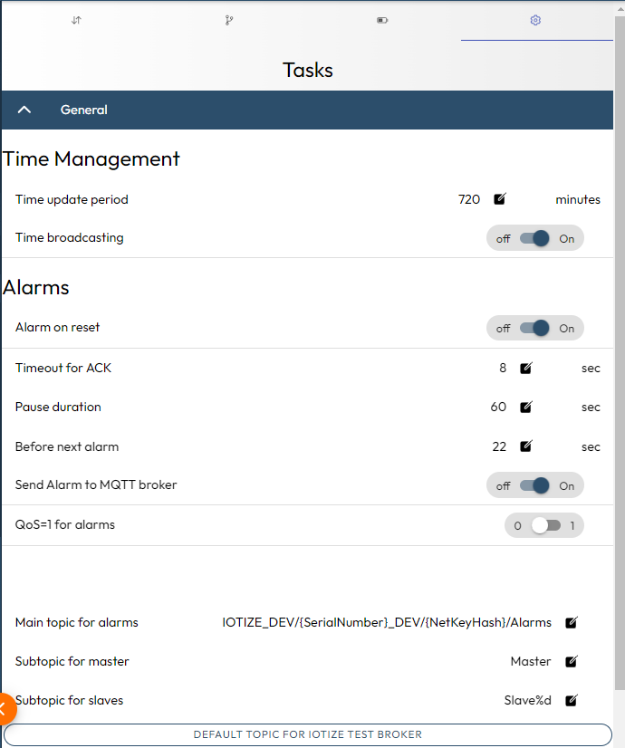
General Settings for Alarms
The following parameters must be specified:
| Parameter | Type | Description |
|---|---|---|
| Alarm on reset | boolean | Indicates whether an alarm is generated at startup (reset) |
| Timeout for ACK | int | Maximum time to wait in seconds for ACK by a slave |
| Pause duration | int | Amount of time in seconds before restarting a non-ACK alarm |
| Before next alarm | int | Wait time in seconds before launching a new alarm after an accepted alarm |
| QoS | boolean | Quality of Service level required from the MQTT broker to send an alarm |
| Main topic for alarms | string | Topic on which alarms are published |
| Subtopic for master | string | Subtopic to be added to the main topic for TapBus-Power |
| Subtopic for slaves | string | Subtopic to be added to the main topic for slave modules |
If you click on the button titled 'Default Topic for IoTize test broker'(when using the Iotize test broker), the Main topic for alarms will be automatically filled.
Battery & System Management
Configuration
In the 'settings' pane, the following parameters can be specified:
| Parameter | Type | Description |
|---|---|---|
| ----Testing----- | ||
| Test period | int | Indicates in minutes the test period (between 2 tests) |
| Enable periodic test | boolean | Enable automatic periodic testing of the battery |
| Alarm on weak state | boolean | Issue an alarm (following a test) when the battery is considered to be low |
| Broadcast on weakstate | boolean | Broadcast a message to slaves (as a result of a test) when the battery is low |
| ----Events------ | ||
| Switch OFF level | int | Low level to switch off the battery (typ. 10V) |
| Alarm on Main Power down | boolean | An alarm is emitted when the main power supply is low (and power coming from battery) |
| Broadcast on Main power down | boolean | Broadcast a message to slaves when the main power supply is low (and power coming from battery) |
| Alarm on power off | boolean | An alarm is emitted when the battery is going to be disconnected (too low) |
| Broadcast on power off | boolean | A message is broadcasted when the battery is going to be disconnected (too low) |
Control
The Battery tab allows you to control the voltage level of the battery as well as its switching.
At the top of the page, the internal voltage (typically 24VDC) and the voltage of the backup battery are displaid. Note that you will get a value for the battery voltage, even when no battery is present (except during testing).
Then the page presents the system information and finally allows you to carry out an immediate battery test by pressing the Test now button.
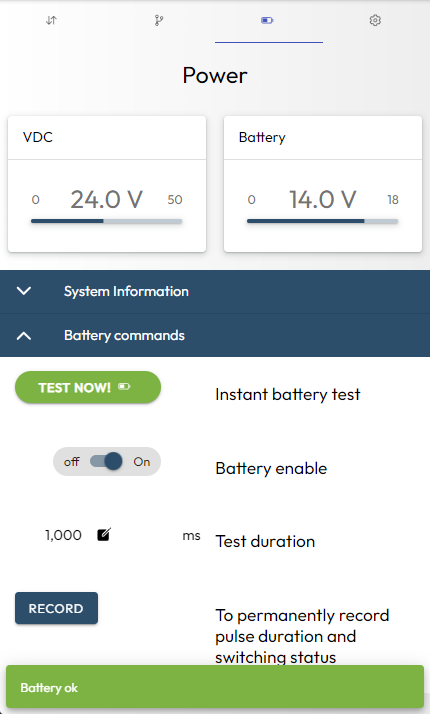
Note that if the Enable battery option is changed (or the duration of the test), it is necessary to click on the Record button to save your changes.
| Parameter | Type | Description |
|---|---|---|
| ----Testing----- | ||
| Instant battery test | button | Run a test and display the result within a toast. |
| Battery enable | boolean | Connect the battery for either recharging or getting energy |
| Test duration | int | Define the duration (in ms) of the test pulse (typ. 1000ms) |
| Record | button | Save in the equipement the values above |
| ----Events------ | ||
| Switch OFF level | int | Low level to switch off the battery (typ. 10V) |
| Alarm on Main Power down | boolean | An alarm is emitted when the main power supply is low (and power coming from battery) |
| Broadcast on Main power down | boolean | Broadcast a message to slaves when the main power supply is low (and power coming from battery) |
| Alarm on power off | boolean | An alarm is emitted when the battery is going to be disconnected (too low) |
| Broadcast on power off | boolean | A message is broadcasted when the battery is going to be disconnected (too low) |
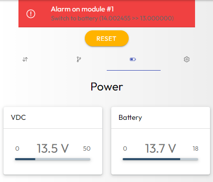
On the screenshot below, you can see that:
- an alarm was generated because the power was cut ('Switch to battery'),
- power is now provided by the backup battery (which has a higher voltage level than the internal VDC voltage).
Manage the list of slave modules
The Bus tab allows to identify new slaves installed on the bus.
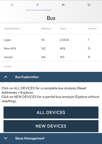
Exploring the bus
The All devices button will clear the current list of devices, then will explore the bus while some new devices are found.
The New devices button will start immediately the search for some new devices (without clearing the current list).
Once the crawl is complete, the table at the top of the page lists the devices found. For each device, you can see: - its name (a module can be renamed on the IOs page), - its modbus address (could be the position when no address is predefined), - its type, - its relative position on the bus.
Setting the slave definition
The name and the address shown in the table above can be changed. The type and the position correspond to physical data and cannot be modified. To modify this data, go to the IOs page and select the module you wish to edit (here the module named 'Logic' at address 161):
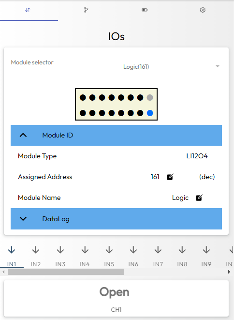
Just click on the pens to edit either Assigned Address and/or Module Name. Once you have changed the modules you want to edit, launch a full analysis and check that all settings are correct.
Alarms
Alarms can be generated either by the master module (TapBus-Power) or by a slave module.
Triggering alarms
In the case of a slave module, we can consider either predefined configurable alarms or alarms linked to custom events. In this case, additional Java code will need to be added. For other alarms, the events that trigger alarms can be defined from the TapBus Manager.
When an alarm is detected at a slave module, the slave module triggers an interrupt on the address line (line added to the modbus link). The TapBus-Power module then detects the origin of the event by measuring the voltage level on this line, and retrieves the information related to the alarm on this module. To do this, it is important not to 'move the slave modules' without performing an exploration that allows the positions to be linked to the addresses of the slave modules.
Alarm Reporting
When an alarm is detected, different states allow it to be visualized:
-
The red LED of the power module flashes,
-
A message appears at the top of the TapBus Manager application.
-
An MQTT message is posted on the MQTT broker.
Of course, the latter option is most often considered, but it requires a remote server to process this message...
Datalog
The datalog consists of sending status information at regular intervals of time. These actions are all handled by Java code that is provided and therefore modifiable. From TapBus Manager, the following settings can be accessed:
-
In the 'Tasks' page, the 'Datalog' accordion allows you to globally validate the datalog, to define the period (common to all modules) of the datalog as well as the formatting: to know if you send a single message for all modules, or one message per module.
-
On the IOs page, there are several options for formatting the sent message. Typically to specify whether it is a JSON file or a simple text in CSV format.
-
At the level of each module, additional parameters can be defined. In particular, the selection of the channels concerned by the datalog. This information depends on the module (please refer to the specific documentation dedicated to your module type).
💡Important note:
For a given module, the length of the datalog message is limited by the size of the modbus register (i.e., 150 bytes). It is always possible to modify this mechanism (or simply the size of the buffer) but any modification will have to be made to the slaves as well as to the power module.
Detailled configuration of the slave modules
This configuration is totally dependent on the part number of the module. Refer to the documentation dedicated to each module to make these configurations:
| Model | Description |
|---|---|
| TpB-IO-AI16 | 16 analog inputs |
| TpB-IO-LI12LO4 | 12 logic inputs, 4 logic outputs |