TpB-IO-LI12LO4 configuration
The TpB-IO-LI12LO4 module offers 12 logic inputs and 4 logic outputs. All inputs are independently configurable, with the same possibilities (and similarly all outputs).
Front board
The front panel contains (as any slave module) an NFC antenna and 16 LEDs (multicolor, RGB).
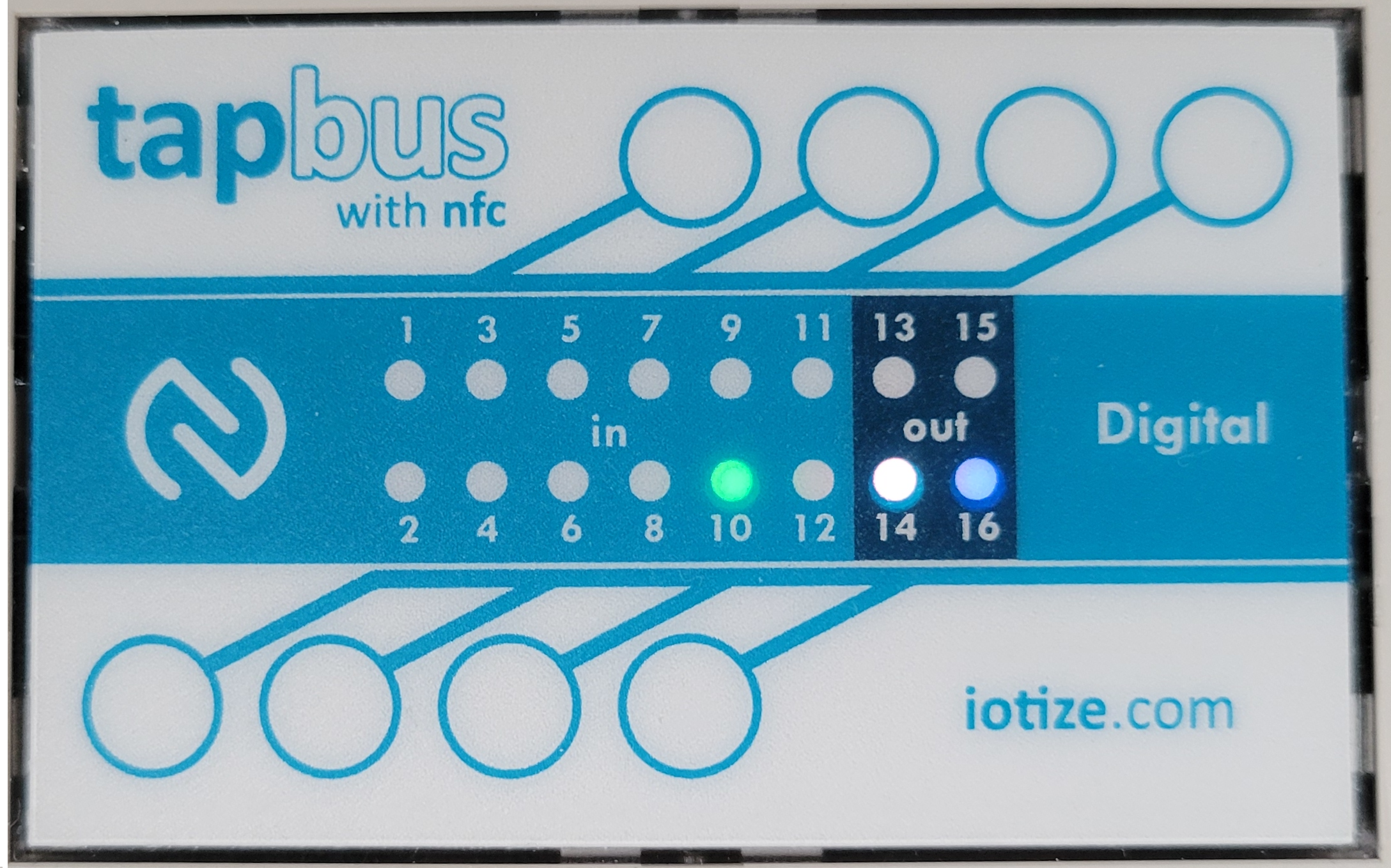
The NFC antenna is at the periphery of the panel.
The 16 LEDs represent the state of each channel. Their behaviour can be modified by Java, but by default:
-
a green LED for an input means that the channel is configured as input and the external contact is closed,
-
a blue LED for an output means that it has been configured and the contact is opened,
-
a white LED means that the contact is closed.
Channel Configuration
It is strongly recommended that you first configure from TapBus manager. Subsequently, configurations can be pre-programmed in order to short-circuit this step.
Input mode
It can be selected from the following:
| Mode | Description |
|---|---|
| Input modes | |
| Input | Default state input (opened or closed) |
| Input-inverted | The behviour of the LED will be inverted |
| Counter up | Incremental counter |
| Counter down | Count any edge, either rising or falling |
| Chrono high | Integrate the time for 'closed state' |
| Chrono low | Integrate the time for 'opened state' |
| Frequency | Frequency measurement |
| Output modes | |
| Output(NC) | Output, active opened(normally closed) |
| Output(NO) | Output, active closed(normally opened) |
| Pulse (NC) | One pulse generation (normally closed) |
| Pulse (NO) | One pulse generation (normally opened) |
| Periodic(NC) | PWM, active opened (normally closed) |
| Periodic(NO) | PWM, active closed (normally opened) |
💡Notes:
-
for counter, chrono, frequency, pulse and periodic modes, the precision is always 1ms. It means that the max input frequency should be less than 500Hz for inputs and 1kHz for outputs.
-
For periodic outputs, the 'normal state' is applied when the signal is not active.
-
For periodic outputs, the duration of both opened and closed states are settable. It means that this signal can be used as a PWM with a 1ms resolution.
-
For inputs, a debouncing value can be defined, again with a resolution of 1ms. This value is used to accept a change of state (considered as effective when the duration of the new state is longer than the debouncing value).
-
For counters, a multiply factor can be apply. It can be used for example with a flow meter if a pulse occures every 25ml (then the multiply factor could be 0.025 if you want to display the measured values in liters).
Store in datalog
Indicates that this specific channel has to be transmitted within a datalog message. Note that the you need to consider the high level settings to enable datalogging.
Alarm settings
An alarm can be generated when a value is going out of the specified range for a counter/frequency, or on a change of state for a simple input.