Make your own dedicated App
To put it simply, there are two extreme ways to make a control application of a 'TapBUS' system:
-
An application that includes the highly configurable aspect of the modules
-
A simple application that assumes a fixed, pre-configured system that accesses known registers.
Here we are dealing with an intermediate case: we will use the default, configurable and generic configuration, and we will add registers specific to the two modules (logical and analog) that we have installed on the railBUS.
Presentation of the system to be controlled
We consider a 3 modules system compound of a TapBUS-Power, a logical TB_LI1204 and an analog TB_AI16:
-
The modbus addresses of the slave modules are known: the logical module TB_LI12O4 and the analog module TB_AI16 are at addresses 161 and 162 respectively.
-
The IO assignments on these modules are known.
On the logic module, we have configured as outputs:
-
IO14 output as logic output
-
IO16 output as PWM output (1500ms OFF, 500ms ON)
and as inputs:
-
IO10 as standard input (dry contact)
-
IO12 as a counting input.
On the analog module, we connected a Pt100 probe (temperature) to IO15 and a 4-20mA anemometer sensor to IO13.
We're going to develop a simple application which allows you:
-
to stop the PWM output on IO16, and to control IO14 (logic module),
-
to display the status of IO10 and the value of the counter on IO12 (logic module).
-
to display the IO13 and IO15 values for both sensors.
Dashboard with ‘Managed Tap Controls’
The layout of the application is shown below:
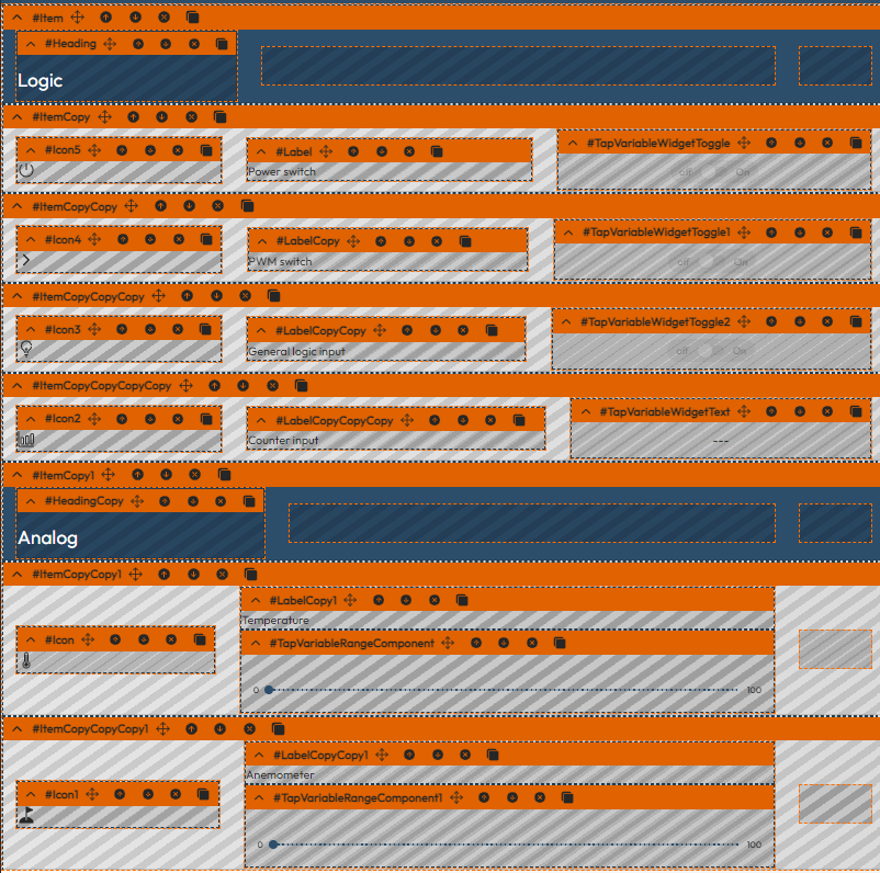
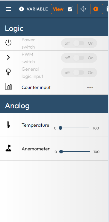
and the preview:
The visualization elements are all 'Managed Tap controls' which will be connected to Tap Variables. The alternative would be to choose simple elements connected to 'direct modbus' nodes. The interest of the 'Managed Tap controls' is to simplify 'read+write' accesses (in particular to modify a single bit), while the interest of the latter would be to use 'direct Modbus' nodes associated with the absolute addresses of the registers that one wishes to read or write.
Define the variables in Studio
In this case, we want to use bitfields within absolute variables. The easiest way is to create an IOTZ file in Studio to receive a list of the variables you want to address. To put it simply, we're going to take the default configuration file of the TapBUS Power module, and add the 'target' registers to it, which are the images of the slave modules' registers.
When working with the TapBUS-Manager application, the 'target' variables are all associated with the slave whose address is '0' (which corresponds to a generic selected slave). In our case, we do not wish to go through a dynamic 'selection', but to address directly the slave registers at the absolute addresses 161 and 162 . So we're going to add these registers back into the configuration file and create the following list of variables:
-
Counter161: slave= 161, latch_register_addr= 0x3100 (fixed image of Counter_input_x3100)
-
Out161: slave= 161, latch_register_addr= 0x3030 (fixed image of Log-output_x3030)
-
Analog input: slave= 162, latch_register_addr= 0x3200 (fixed image of Analog_Input_x3200)
The table below summarize their characteristics:
| Name | Slave Address | Register address | Type and size | Quantity |
|---|---|---|---|---|
| Counter161 | 0xA1 (161) | 0x3100 | uint32,holding reg | 16 |
| AnaIn162 | 0xA2 (162) | 0x3200 | float,holding reg | 16 |
| Out161 | 0xA1 (161) | 0x3030 | uint32,holding reg | 1 |
With Iotize Studio, we open the PowerTpl.iotz file in C:\Program Files (x86)\IoTize\IoTize Studio\Examples\TapBus\TB_Power
The Save as command allows you to copy (and rename) it as Example.iotz to the c:\tmp\TapBUS_Example\ directory.
The PowerTpl.java file is also manually copied to the same directory.
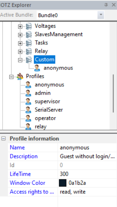
Let's add a Custom bundle to this directory. To simplify, let's give write and read access to the anonymous profile for this directory.
The generic variables are already present in the SlavesManagement bundle. Just create the new ones again in Custom, with the same characteristics, but with a Slave address of 161 for the variables of the logic module and 162 for those of the analog module. Next, let's add the variables:
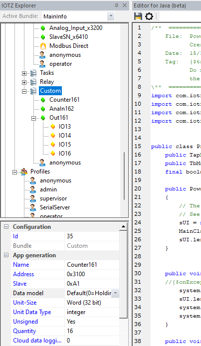
For the last variable (Log-output_x3030), we add now the 4 bitfields that correspond to IO13...IO16 and configure the TapBUS-Power module with the new configuration (after compiling the Java file).
Import the variables into the App
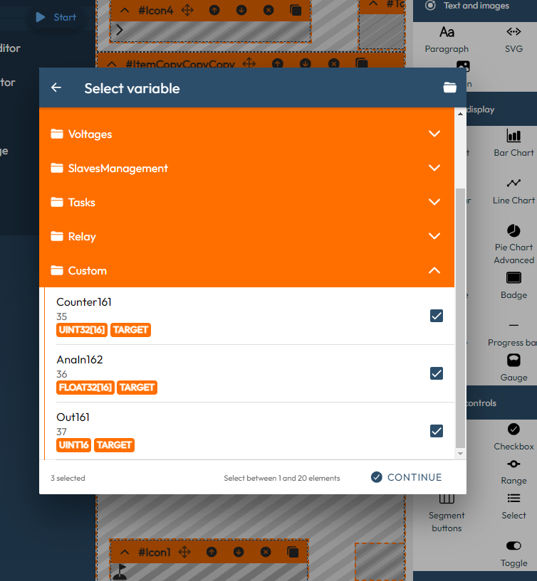
Once your IOTZ file has been saved, you can import it in App Creator. Click on Resource Files in the left menu, then select the Example.iotz files. In the Dashboard Editor, click on the Variables button at the left of the View menu, then select the variables located in the Custom accordion:
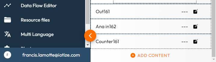
The 3 new variables appear as 3 Number Input component at the bottom of the page, in the Dasgboard Editor:
and a simple dataflow has been also created:
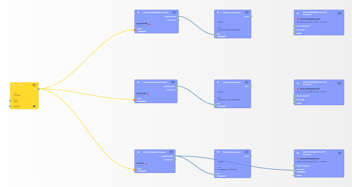
On this dataflow, we see:
-
a ticker on the left,
-
then the 3 TapVariable associated with 3 Value extractors
-
and on the right, 3 GUI component that are the Number Input created at the bottom of the dashboard. Note that only one of the 3 is connected because these GUI component can display a simple element while the 2 unlinked TapVariables are arrays of 16 elements.
Anyway, we don't need neither the extractors, nor the new GUI components and we delete them (we just keep the ticker and the 3 TapVariables).
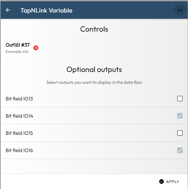
In the settings of the Out161 TapVariable, we select the IO14 and IO16 bits:
and we also select variable[13] and variable[15] for the AnaIn162 TapVariable, and variable[9] and variable[11] for the Counter161 TapVariable.
Then we go to the dashboard and click on the small 'Flash' icon for each GUI component we want to control from the dataflow (the sliders, the toggles and the text output). We can now connect the Tap Variable inputs of these GUI component nodes to the output of the variables we just added (variable[9] and variable[11] for the Counter161 TapVariable, etc).
We now have the following graph in the dataflow:
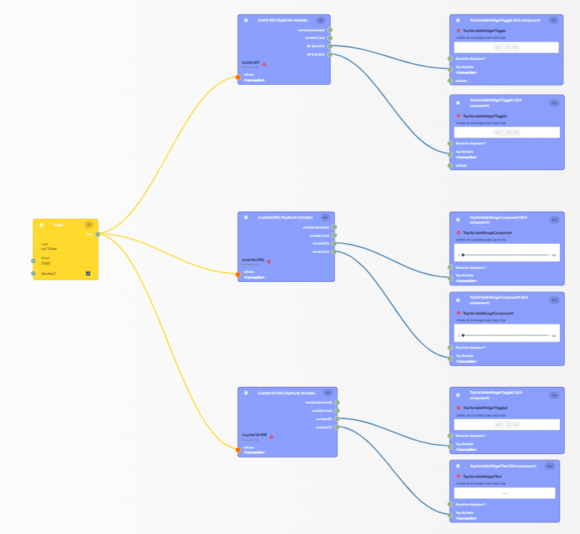
Thus, each visual component is now connected to a Tap Variable: either a bitfield, or an element of an array. In the finalproject (available in the Samples folder in TapCloud) you will see that the analog values are also output as text fields.
Run and improve the App
If you launch the App and you connect to your TapBUS Power, you will see:
You now have a very simple mobile app, dedicated to our system. As the generic application is more complex in use, it is such an application that can be implemented by an end user. To improve the App you can:
-
Associate your TapBUS Power with either the dynamic dashboard you can deploy, or the static application you can also generate.
-
Modify the ACL (access rights) to disable the generic accesses and permit only to read/write what you decide, for the right persons.
-
If you need, you can also modify the embedded Javza programs to perform some actions, or setup datalog or alarms.
Where to find the example
-
The IOTZ file is delivered in the TapBUS examples, in IoTize Studio (accessible for free),
-
The App Creator project is also available for free, but in the Samples tab when you open a Dashboard Editor. The static Apps are not on the stores, but you can generate them from this project.