Manuals/App Creator/Getting Started
IoT App Creator: Getting Started
Introduction
We see here, how to build step by step a simple App by using App Creator:
We assume that you have already read the documentation for the Dashboard and the Dataflow editors, but we detail most of the operations.
The necessary hardware and the software tools
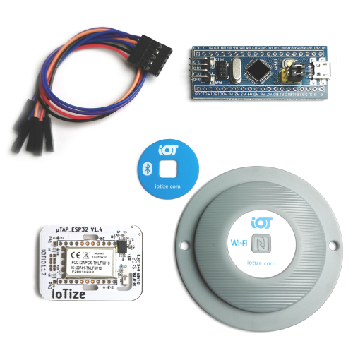
For this introduction, we use below a standard 'Primer Kit' that contains:
-
A TapNLink Primer (either NFC+BLE or NFC+WiFi+BLE),
-
A simple demo board (bluepill based on a STM32F103),
-
A 5-wire cable to connect these two boards together as described here.
We assume that:
-
You downloaded from the IoTize web site the IoTize Studio application and installed it on a Windows computer,
-
The TapNLink is configured with the'SensorDemo.iotz' configuration file available by default here:
{Program Files}\IoTize\IoTize Studio\Examples\Sensors_STM32_Demo
-
The Bluepill board is programmed with the default 'SensorDemo.elf' firmware you will find here:
{Program Files}\IoTize\IoTize Studio\Examples\Sensors_STM32_Demo\Sensor_tem\out
The main tool we will use for this tutorial is the Tap Manager application. We will use two different versions of this tool:
-
A mobile version (either for Android or iOS) available on the Play/App stores.
-
A Web App version available at https://tap-manager-beta.web.app
This version will be used to create/edit the App. To run this Web Application, we just need a browser that supports BLE (for example recent versions of Chrome, Edge or Opera). Note that the Android/iOS version are equivalent to the Web App, but a large computer monitor and a mouse are highly recommended to work with App Creator (even if all operations are executable on an Android device).
-
Once Tap Manager has been started, you have to create a free account on Tap Cloud (mandatory to store your project file and to generate your App):
-
launch Tap Manager from Chrome (for example),
-
Create an account by signing in,
-
Once the account created, you can either modify your plan to extend your rights, or create an unique workspace for a single demo project. Let's consider this case.
-
How to build a first App with the Dashboard Editor
App Creator consists of two parts: a Dashboard Editor and a Dataflow Editor. At first, you can work with the only Dashboard Editor. Using the Dataflow Editor will become mandatory as soon as you will add more complex features.
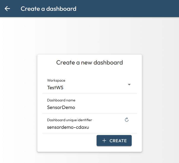
Create a new project
By selecting the ‘Dynamic dashboard’ section on the right, you get the list of your dashboards already built. If you open this list for the first time, it will most certainly be empty and you can create your first project by clicking on the ‘+’ button at the bottom right:
then we have a choice between:
-
create a dashboard from scratch.
-
create a dasboard from an IoTize Studio file (.IOTZ),
-
or copy open the Sensor Demo to analyze it.
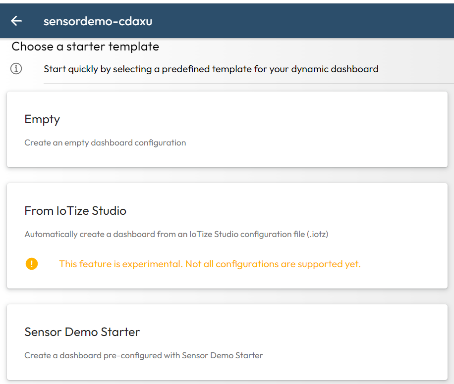
Lets select the 'from IoTize Studio' solution and pick the following file from the Studio examples:
C:\Program Files (x86)\IoTize\IoTize Studio\Examples\Sensors_STM32_Demo\Sensor_demo.iotz
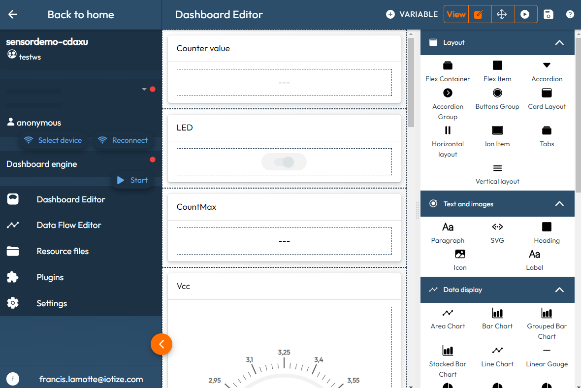
We obtain a first dashboard with all the variables selected in a simple list:
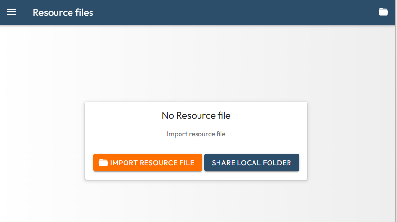
Add resource files
If you followed the previous the recommendation of the previous section and you loaded an IOTZ file, go to the next paragraph. If you preferred to create an empty project, you will have then to specify some resource files:
If we consider the example of the ‘Sensor Demo’ project, we can import:
-
Either the 'ELF' file available after installing IoTize Studio (in 'C:\Program Files (x86)\IoTize\IoTize Studio\Examples\Sensors_STM32_Demo\Sensor_tem\out').
-
Either the 'IOTZ' file (configuration for Studio) available in 'C:\Program Files (x86)\IoTize\IoTize Studio\Examples\Sensors_STM32_Demo'.
If we choose the ELF file, we will have to work using the 'direct SWD' protocol. If you choose the IOTZ file, we retrieve the entire configuration (including bundles and user profiles). We strongly recommend to use the IOTZ file. In the dictionary files such as ELF/DBC/CSV files we find only the raw addresses (32-bit for ELF) of the variables. Therefore, addresses are the only way to access the variables and you will need to be logged as administrator to use an 'address-based protocol' such as SWD-direct, Modbus-direct... Moreover, the address for the ELF files are quite unstable and could move when linking. If you work with the IOTZ file, you will not depend on the relocation process (the variable indexes are stable).
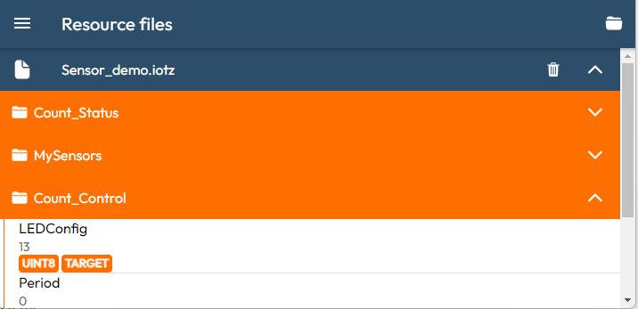
Take the IOTZ file (the one used to configure the Primer).
We now find the list of variables used in the resources classified by bundles:
Define the main layout
After importing an IOTZ file, each of the variables are inserted into a 'Card layout'. To organize the presentation of these variables, we create the main layout, i.e. define how the page being edited will be organized.
Let's take a 'Tabs' component in the layout section on the right, and place it above the first card (top of the list). This action can be performed:
-
either by clicking on the orange ‘Add content’ button at the bottom of the page. Then, move up this new component to place it at the top,
-
or by selecting the 'Tabs' component from the list (on the right) of available layout components, and by placing it with a drag and drop operation:
We obtain a page with a 'Tabs' element to which we can add sub-tabs:
-
for example by clicking on the NEW button of the Settings panel (the Tabs component must be selected),
-
or by pressing the '+' at the level of the component placed on the Preview window.
Note that a container of 'Tabs' can only contain 'Tab' sub-elements, while most of the other 'layout' type components are much more tolerant containers.
So let's keep our two Tabs. By default they are named 'My first Tab' and 'My second Tab' but we can rename them to 'Sensors' and 'LED' in the Settings panel. It is also possible to add icons to each Tab by clicking on the ‘Select’ button next to the Ionic icon text.
Organize the tabs
The edit page then shows us the two 'Tabs' available. The presence of overlaid tabs is simulated in the editor and the 'Add Content' button present under the 'Tabs' concerns only the active Tab (currently selected, not all of the two available Tabs). Once you have selected the right Tab, you can 'drag and drop' the following Card layout components that contain our variables to this specific Tab, as follows:
| Variable | Destination Tab |
|---|---|
| Counter Value | => LED |
| LED | => LED |
| Vcc | => Sensors |
| Temperature | => Sensors |
| MaxTemp | => Sensors |
| Blink period | => LED |
| CountMax | => LED |