Target protocols
Several types of wireline links are possible between TapNLink and the target microcontroller. IoTize Studio offers 4 target protocols:
- SWD
- S3P
- Modbus
- Standard Serial
The first three are managed in very similar ways. Standard Serial is different, it depends on which Modbus physical level is being used, it is placed here because it is often chosen by TapNPass users.
2 other protocols are in the list but are unavailable:
-
Custom protocol: customer specific
-
DirectIO: being developed for general access.
Electrical connection and characteristics
See TapNLink user manual for information about hardware (connectors, cable and electrical characteristics).
Protocol direction
Most of the communication protocols consider two protagonists that are generally qualified as:
- master and slave,
- sender and receiver,
- upstream and downstream,
- ...
Generally, the 'master' sends a requests such as 'read' or 'write' (could be in our case 'GET' of 'PUT') and the slave answers. For the protocol established between a TapNLink module and a target board, it is generally the same: one sends a 'GET variable' command and the other answers with the contents of the variable.
In most of the supported protocol, we generally consider the TapNLink module as the master, and the target processor as the slave. Therefore, your target board will have to answer to requests sent by the Tap. For example, you firmware features a variable named 'temperature' and the Tap will send a request 'Get the temperature variable'.
However, it is also possible to consider the opposite: the Tap can contain some 'InTap' variables, and in that case, your firmware will have to send requests to read/write these variables.
A protocol that accepts both directions is qualified below as 'reversible'.
Protocol levels
There are 3 levels of Protocol management that access:
- Communication functions ('physical' level).
- Addressable spaces ('protocol' level).
- Variables ('application' level).
These levels can be characterized by API functions:
| Level | Type of access | Reading | Writing |
|---|---|---|---|
| 1: Physical | Communications | char getchar () ; |
putchar(val) ; |
| 2: Protocol | Addressable spaces | int read (addr) ; |
write(addr, val) ; |
| 3: Application | Variable sets | Int readvar(" xvar ") ; |
writevar(" xvar ", val) ; |
In practice, the application level calls the protocol level which calls the physical level, so for example:
- When calling the function
readVar (COUNT) level 3, - the Tap searches the list of registered variables for COUNTs addr_count address.
- It then calls the
read (addr_count)function that corresponds to the lower level. - If we assume the protocol used is Modbus,
- the Tap translates the function
read (addr_count) level 2by sending a frame that asks the target for the value of the register whose index isaddr_count. - the Tap uses the
putcharfunction of the UART to send the frame { 1, 3, ...} and uses thegetcharfunction to receive a frame containing the desired value.
Cross-reference of levels and IoTize Studio protocols:
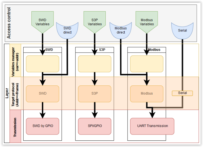
Note that three entry points have been added (see IoTize Studio config for details):
- Serial
- SWD Direct
- Modbus Direct
They differ from the general entry points (S3P / SWD / Modbus) because they allow you to manage the protocol levels directly using addresses (not variables), manage the physical level for Serial, and provide debug access for a target firmware update using SWD Direct.
Access protocols for variables
IoTize Studio offers three protocols to access variables:
- SWD
- S3P
- Modbus
The table below compares their main characteristics:
| SWD | S3P | Modbus | |
|---|---|---|---|
| Target core | Cortex-M only | Any | Any |
| HW resources | Debug port | 2 GPIOs + one IRQ (could be debug port) | UART (incl. 2 GPIOs and IRQ) |
| Implementation time | A few minutes | A few hours | A few hours |
| Intrusivity (CPU resources) | None | Typ. 100 us per access | Typ. 100 us per access |
| Intrusivity (ROM resources) | None | Typ. 2 KB | Typ. 3 KB |
| Security | Debug port could be an issue | Good and scalable | Good and scalable |
| Distance (TapNLink to target) | Max 1m | Max 1m | Max 1m (more with a transceiver) |
| Special features | Make easy FW update and remote debugging | - | - |
| Variables access | Absolute | Indexed or absolute | Indexed |
| Reversibility | NO | YES | YES |
The interest of accessing variables
TapNLinks management of variables has several advantages:
- The developer simply retrieves the variables from his firmware.
- for SWD, S3P and Modbus, IoTize Studio directly reads ELF files (application firmware) and retrieves both variable names and types.
- for S3P and Modbus, IoTize Studio automatically generates the files necessary to take into account the protocols in the firmware of the embedded application.
- Bundle management allows to group and organize the variables according to their use.
- Access control applied to each bundle allows easy distribution of access types: read and/or write.
- API functions allow these variables to be immediately retrieved from GUIs, regardless of their type (or size).
- Special functions such as datalog and alarm detection are available.
All these points are managed at TapNLink level in order to facilitate and secure the construction of the global application.
Absolute vs Indexed access
S3P and Modbus allow indexed access. This means that instead of addressing a variable at address 0x2001ABC8, TapNLink looks for the nth variable in an array of predefined variables.
This index is unaffected by firmware changes that could lead to a new mapping of variables, and configuration changes, because IoTize Studio maintains the indexes (as long as the variables are not deleted from the list).
Indexed mode therefore has the advantages of:
- stability and reliability.
- security, because only the variables in the table are accessible, regardless of the profile and rights of the connected user.
SWD protocol
The SWD protocol is the debug protocol most often used with microcontrollers with a Cortex-M core.
The main advantages are:
- Non-intrusive: you can read or write a variable without the target application noticing.
- This port is often available because it is only useful for initial programming.
- No software or hardware modifications are required normally (except to make the debug port available when it is not).
- Allows you to easily perform software updates remotely. It is therefore perfect for creating a PoC by integrating a TapNLink in a few minutes on an existing system.
The main disadvantages are:
- Leaving the debug available on a final application would also allow a competitor to review the binary code. Depending on the application, this can either be considered as inconsequential or as a potential security breach.
- Synchronization between the TapNLink configuration and the target firmware is required because indexed mode is not possible in SWD.
S3P protocol
The S3P protocol is an alternative to SWD and improves certain features:
- Like SWD, it requires two GPIOs. Very often, when the debug port is disabled, the two SWD GPIOs remain unused (this is true on all STM32s, but not on all Cortex-Ms).
- S3P allows an indexed mode.
- Security procedures are easily implemented in S3P.
In general, it is recommended to start with SWD, then move to S3P for an industrial version. For implementation, an application note and examples allow you to easily add the S3P agent within your application. This is a summary:
- Add files to your project (including a file generated by IoTize Studio)
- Validate the interruption associated with the S3P-CLK signal.
It should also be noted that two "sub-modes" are available for IoTize Studio:
- Indexed mode: the preferred mode.
- SWD-emulation mode: variables are addressed by their absolute addresses. It is therefore very close to SWD and has the same potential security vulnerabilities. It is provided as it offers an intermediate step in a migration between pure SWD and indexed S3P.
Modbus protocol
Modbus is considered as the industry standard and is generally integrated into serial interfaces used for equipment control and configuration. The physical support is then an RS-485 or RS-232 link (as with TapNPass).
When TapNLink is connected to a target microcontroller the link is also serial, but compatible with the voltage levels of the GPIOs (between 2.5V and 3.3V).
IoTize Studio generates source files which can be used for a quick implementation.
Additional resources are required:
- An available UART,
- Reception must be managed by interruption. The sources provided are based on the standard implementation specified by modbus.org. They must be complemented by a hardware-specific configuration to provide low-level communication and timer functions.
Coding the protocols
IoTize provides tools to make as simple as possible the task of coding these protocols:
- at the side of the TapNLink module, the Duetware firmware already supports the proposed protocols. The only thing to do is 'configuration'.
- for the SWD protocol that is handled by hardware on Cortex-M (ARM core) microcontrollers, there is nothing to do. The variables are accessible 'on-the-fly' without modifying your firmware.
- for the other protocols (S3P and Modbus), some pieces of code are automatically generated by IoTize Studio. These sources files have to be compiled and linked within your existing firmware.
- in 'revert mode' (e.g. when the TapNLink is considered as a slave and the target board writes the Intap variables), some examples are provided. You will have to copy and paste these examples in your project, then decide which variables you need to read/write.
Communicate "without variables'
It is possible to bypass the management of variables by:
- Direct access to the address map. This mode is of little interest except for debugging in SWD, or allowing global Modbus access (independent of the target) with a product like TapNPass.
- Direct access to the physical communication port. In principle, only UART is available so TapNLink would be a simple secure communication relay, and the protocol content would be unknown to the TapNLink because it is managed at the target firmware level.
Configuration from IoTize Studio
Target protocol can be selected in the "IOTZ Explorer" panel: IoTized Application | Target | Link TargetTap | Target Protocol.
You can select SWD, S3P, Modbus or Serial (see the central row in the cross-reference diagram).
Extra rights can be added by adding the protocol directly to a bundle (from features in the "Resource view" panel):
- SWD Direct: allows a debugger to establish a debugging or programming session for the target firmware (if the users profile is associated with the bundle).
- Modbus Direct: the authorized user can execute API functions that give access to any Modbus register (regardless of variables access rights).
- Serial: gives associated profiles rights to use this generic serial link.