TapNPass User Manual
This documentation covers details that are not covered in the Getting started.
Introduction
The TapNPass provides radio access to systems with a serial connector, thus removing the need for cables. It adapts easily to existing systems that were not designed for wireless communication. The TapNPass provides RF access via a mobile device to monitor or configure existing electronic systems and is available in 2 versions, Nomad and Fix.
Nomad and Fixed compare
| Nomad | Fixed |
|---|---|
| Can be used with different systems | Dedicated to one system |
| Equipped with rechargeable batteries for a long autonomy and designed to be easily moved from one system to another | Equipped with a power supply connector and designed to be installed close to a specific machine |
 |
 |
In this documentation, if a paragraph applies to one version only, the version is explicitly indicated.
RF access
- TapNPass supports NFC and BLE communication channels, which can be combined to provide consumption and security advantages.
- See RF host protocols (NFC, BLE, WiFI...) for RF channel details (consumption, range, data transfert rate, etc).
- See UserManuals/Security for NFC pairing details.
Monitoring your target system from your mobile device
The TapNPass embeds a TapNLink module that is easily configured in IoTize Studio to convert your mobile device into a powerful Human Machine Interface for your system:
- For a Modbus interface, you can generate a simple Web app in minutes, using the HTML pages generator included in IoTize Studio.
- For other interfaces, working examples are provided, with APIs that facilitate native application development. See Mobile Development for method details and related tools.
Watch this video tutorial to show how generate a mobile app for a product that is equipped with a TapNPass wireless-Modbus adapter. The app communicates with a device through the TapNPass, using Modbus-RTU communication protocol.
Users
The TapNPass can be configured for specific equipment and dedicated to a specific usage, so there are 2 user types:
-
The end-user (of a pre-configured TapNPass) who needs to know how to:
- turn it on and off
- manage the battery (Nomad)
-
use your Monitoring app
-
The developer who needs to customize a TapNPass to:
-
rapidly develop Apps that monitor Modbus systems, using a native Modbus RTU driver (master)
- link a mobile device to a target system (with same protocol) simply and securely
- set the options, such as:
- general communication parameters: baud rate, parity, ...
- communication mode: Modbus access or transparent mode,
- security mechanisms
- etc
List of materials
This list describes the standard delivery.
- Nomad TapNPass or Fixed TapNPass which have slightly different contents.
- Software, Apps and APIs
Nomad TapNPass
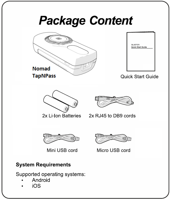
The outer carton contains:
- A TapNPass Nomad case with its electronic boards
- A mini-USB cable for only serial communication
- Two RJ45 <=> DB9 cables for serial communication: one for RS-232 and one (with a blue identifier) for RS-485
- A micro-USB cable that can be used for two purposes: either to recharge the Li-Ion batteries, or to communicate with a machine equipped with a compatible connector.
- Two rechargeable Li-Ion batteries. Read the Safety chapter in the appendix.
Install batteries
To install the batteries, turn the TapNPass over, press on the center of the case, then slide and lift to remove the back cover.
Insert the provided rechargeable Li-Ion batteries in the battery compartment. They must be in the same direction that is engraved into the plastic and shown in the picture below:


Replace batteries
If battery replacement is necessary, replace both batteries. Use only 800mAh AA-size (14500) Li-Ion protected rechargeable batteries:
- Nominal voltage: 3.7V
- Dimensions: 14 x 51mm
- Max charge current: 1.5C
- Max discharge current: 2C
DO NOT USE other types of rechargeable or non-rechargeable AA size batteries. TapNPass does not work with such batteries.
- 14500 batteries are generally 50mm long, but many are over 51mm.
- We recommend to use the branded "Soshine" batteries that fit with the characteristics above.
Charge batteries
Connect TapNPass's micro-USB port to a USB port of a PC (or a charger for mobile) and fully charge the batteries before use.
- Typical charging time is 1 hour.
- The battery charge indicator (green) LED turns off when the battery is fully charged.
- Note that the battery charge indicator LED will blink red if the battery is under 20% of full capacity.
- When the battery capacity is under 10% of full capacity, the power will automatically turn off to prevent damage to batteries.
Fixed TapNPass
The contents are similar to the Nomad, with the same cables (but no USB cord) and the following differences:
- Some screws are provided to allow the TapNPass to be fixed
- Fixed TapNPass does not have a battery compartment, nor batteries...
- A male connector is provided to connect an external power supply (voltage in the range of [10V-30V]). It is next to the USB-A connector. The two-contact female connector (Molex 039530-0002) must be removed to insert the wires from the power source.

We recommend connecting a power source of 5W (12V/400mA or 24V/200mA). Use 2.5mm² wires to provide a power source of 12V or 24V (up to 30V). Note that the polarity does not matter, since the voltage input is equipped with a bridge rectifier.
The TapNPass itself is a low power device (typically 200 mW), but overall consumption depends on the connected devices. If you connect a USB device on the USB-A port, it could consume up to 2.5W (5V - 500mA). The following consumption was measured on a TapNPass Nomad with a 5V source:
- RS-232: 35mA
- RS-485: 45mA
- USB: 110mA (with a FTDI or CP210x connected cable).
Connectors
The RJ-45 connector on the top of the casing is dedicated to pure serial connections: RS-232 and RS-485 signals are mixed as described in the appendices (note that the RJ45 is NOT an Internet connection).


The USB-A connector on the bottom of the casing is a "host USB connector".
Software, Apps and APIs
- IoTize Studio reference manual details how to download IoTize Studio configuration software
- The free apps (Tap Mananger, IoTize Toolbox) can be found in Google Play Store
- The TapNPass preconfigured app, IoTize Toolbox, is automatically accessed when you "tap" your TapNPass with your mobile device to
- configure some communication settings dynamically (baud rate etc),
- test communication.
- After configuring an app, a new app reference (AAR for Android) can be written in the NFC tag of your TapNPass (so as to launch your own app).
Power management
The Nomad TapNPass requires that the batteries are charged, and the cables are connected, before the device is powered up.
Power up
Just press the push button. The LEDs all light-up for two seconds before you can use your TapNPass. Note: TapNPass Nomad automatically switches off after 10 minutes of inactivity. This duration is configurable.
Power off
A long press (more than 2 seconds) of the push button lights the 3 LEDs, and the power switches off when the button is released.
This action can be disabled in the Fixed version, and the device can be powered off either by software (from an authorized mobile device) or when the power connector is disconnected.
Note: the power must be ON to use the data logging feature of TapNPass.
LEDs
The TapNPass features 3 LEDs above the push button. They display (from top to bottom):
- Communication activity (Blue/Orange)
- Battery state (Green/Red)
- Power status (Green)
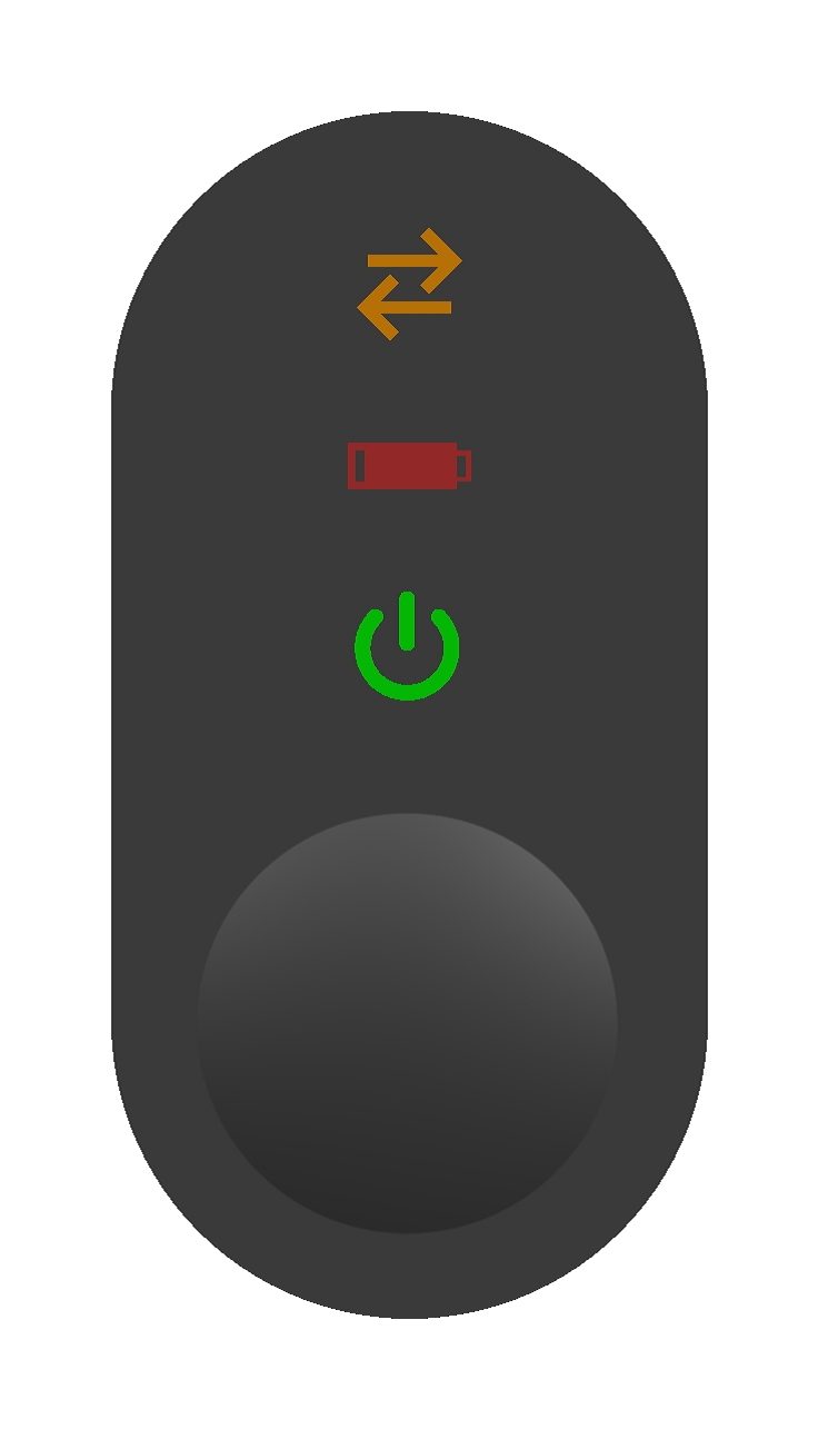
The power LED blinks in a "ramping up" mode when the device is powered.
The battery LED shows (Nomad only):
- Green: battery is recharging (Nomad).
- Red low frequency blinking: battery charge < 10%. In this situation, the power LED is turned off.
The communication LED shows:
- Orange: incoming data transfer.
- Blue: outgoing data transfer.
Particular combinations indicate particular events or states:
- AVAILABLE: blue LED 'ramps up' to indicate TapNPass is NOT connected to a mobile (but is available for a connection).
- CONNECTED: blue and orange LEDs blink alternately (@1Hz during 2s) when the connection is established.
- OVERCURRENT: red battery LED blinking (@ 1Hz) indicates the current consumed by an external device connected to the USB port was higher than 500mA, so the USB connection was switched off to avoid damage.
- IDENTIFICATION: an API can send a message to the connected TapNPass to make all the LEDs blink synchronously for 5 seconds (@5Hz). This state is useful to identify a specific device when several are installed in the same area.
Serial communication ports
The TapNPass provides:
- 2 communication channels on the RJ45 connector
- Two RJ45-to-DB9 cables are provided to use the RS-232 and RS-485 channels
- They differ by their pinning and length:
- RS-232 is 40cm long
- RS-485 is 50cm long with a blue ring identifier around the cable
- One communication channel on the USB host port
RS-232
The RS-232 port is available on the RJ45 connector using its standard RJ45-to-DB9 cable. Note that both RJ45 and DB9 pinouts comply with the standard RS-232-MODBUS specification.
- Baudrates from 1200bps to 300kbps are supported
- Frame: length (7/8/bit) and parity (none, odd, even), acknowledge (CTS/RTS) are selectable.
RS-485
The resistor must be switched on when TapNPass is placed at the end of a long chain.
- The same baudrates and frames as RS-232 are supported.
-
The RS-485 port is available on the RJ45 connector using its RJ45-to-DB9 cable (with blue ring identifier).
-
RJ45 and DB9 pinouts comply with the RS-485-MODBUS standard.
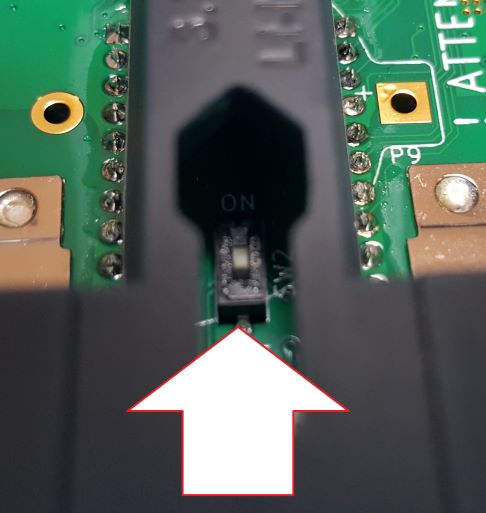
- When communicating through the RS-485 channel, it is possible to add a termination resistor of 120 ohms to reduce noise. A micro-switch is accessible on the Nomad version after removing the battery cover:
Nomad termination resistor
The switch can be turned by inserting a small screw driver in the hole reserved for clipping the back cover into the frame:
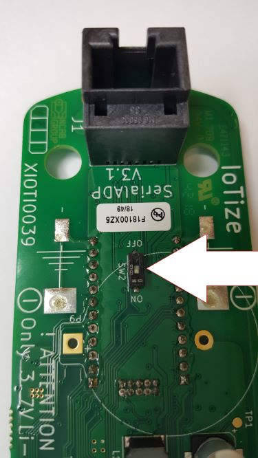
Fix termination resistor
The electronic board must be removed from the plastic case in order to modify the switch position.
Serial USB
The HOST USB-A connector (USB 2.0) can supply up to 500mA to a connected device. It can drive several USB-to-UART converters:
- FT232x (from FTDI Chip)
- CP210x (from Silabs)
- Any USB communications device class (CDC) compliant device.
IoTize Studio serial port config
-
Open menu 'IoTized Application / Tap'. View Link Target <=> Tap underneath. The serial port options are as follows: RS-485, RS-232, USB, AUTO (if AUTO, USB mode is set if a USB device is detected, otherwise RS-232 is set).
-
These settings can be changed dynamically (but these changes are lost when your TapNPass is powered off):
- from your own app, which includes this API
- from IoTize Toolbox.
Connect to a mobile device with IoTize Toolbox
There are several ways to connect a TapNPass to a mobile device, IoTize Toolbox is the simplest. Refer to Mobile Development for mobile development methods.
- TapNPass is pre-configured to launch IoTize Toolbox, a simple app that allows to enter a string to be transmitted to the target and to display the answer.
- The IoTize Toolbox app can also change the default settings dynamically (baudrate, parity etc), and test serial communication.
- Other apps can also be attached to your TapNPass: just configure the AAR stored in the NFC tag of your TapNPass so that the desired app is installed/launched automatically when you tap your TapNPass.
Install IoTize Toolbox
-
Enable NFC on your mobile device, and locate its NFC antenna.
-
Power up your TapNPass, and 'tap' the NFC logo (at the center of the circle engraved on the top cover of the casing) with your mobile near its NFC antenna.
After tapping, your mobile opens the specific page on Google Play (or Apple store) to download the app (if not already installed).
If your mobile does not support NFC, download IoTize Toolbox from Google Play or Apple Store.
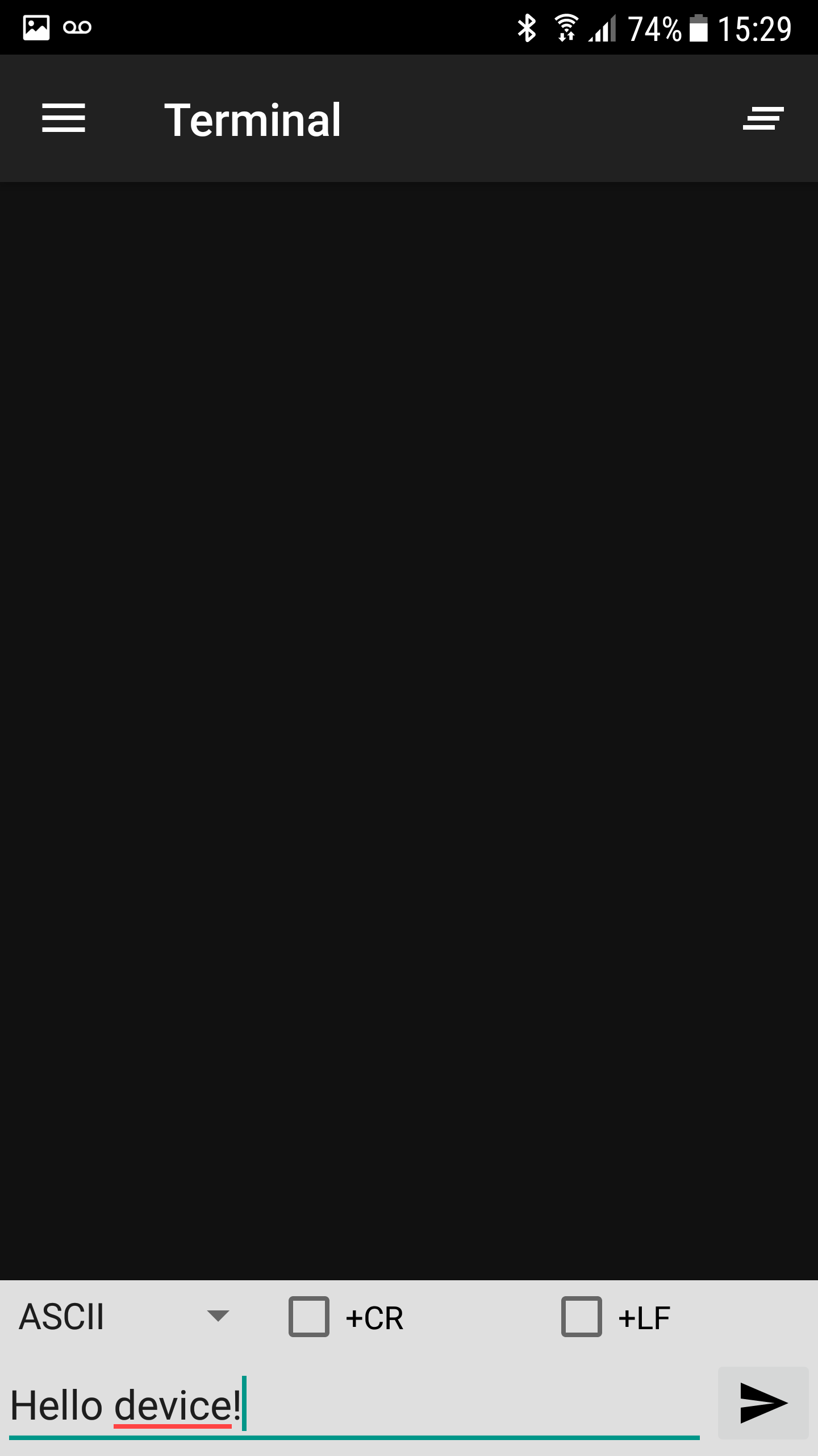
Communicate with IoTize Toolbox
Launch the app by either:
- Tapping the NFC again,
- Running the app from the list of installed apps.
Character strings (ASCII or hex) can be entered and transmitted from this application. The incoming flow is also displayed:
Communication settings are accessed from the main menu (button with three horizontal bars in the top right).
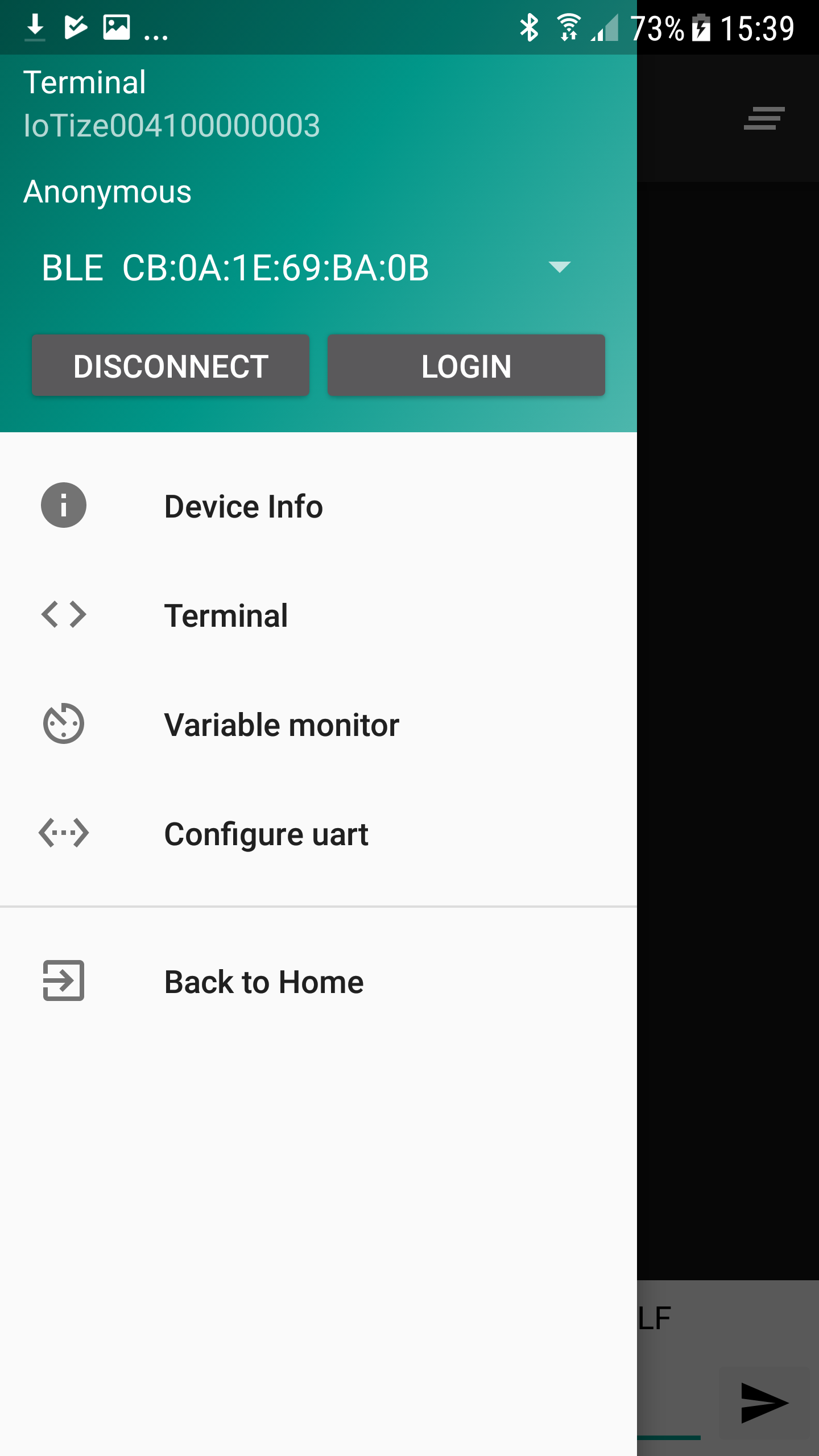
To clear the content of the window, click the button in the top right.
TapNPass Configuration
In IoTize Studio, you can define the way TapNPass communicates with the target system:
- Expand IoTized Application/Target.
- View the related settings in the Target pane underneath:
- Type of Target: Select System (TapNPass).
- SVD/XML pathname (feature unavailable)
- path to XML file containing address and size of ModBus registers. Will be available in future versions, and the syntax will be detailed then.
You can also modify these communication options dynamically:
- from your custom mobile app, using the relevant librairies and APIs
- from IoTize Toolbox.
Target Communication Modes
TapNPass has 2 main communication modes: Modbus and Serial Standard, selected in Target protocol settings.
Modbus
- TapNPass and the target communicate using Modbus RTU communication protocol.
- TapNPass is a Modbus Master and the target a Modbus Slave.
- TapNPass can access 'modbus registers' which can be attached to 'bundles'.
- Access can be restricted (read and/or write) for each combination profile / bundle (see Access Control).
- IoTize Studio's Web App generator can automatically generate HTML pages, providing access to these 'modbus registers'.
- Modbus registers can be logged and handled by APIs.
- Settings:
- Slave Address: If the Modbus communication is between one Master (TapNPass) and one Slave(Target system), you provide the Slave unit address to be used as the default address for commands.
- Timeout: Response timeout (unit = 1/10 s).
Serial
- TapNPass uses a serial stream between the target system and the mobile app.
- TapNPass could be considered as a 'lockable secure cable'.
- Protocol layers should be handled at the application level.
- Settings:
- Baudrate: communication speed in bps. Select Custom to specify a value greater than 300bps and less than 300kbps.
- Parity: check bit for error detection.
- Length: number of data bits.
- Stop bits: end of characters number of bits.
- Handshake: synchronization handshaking.
The settings Identification with LEDs and Enable LEDs can be ignored in this version.
Access Control
Profile-based access control in TapNPass ensures that users only access authorized target resources. The information which follows focuses on TapNPass options. For other Access Control details see:
- UserManuals/Security: detailed underlying mechanisms, bundles, resources, profiles, users.
- Serial and Modbus: configuration examples in the TapNPass Getting started.
Resources
The resources that could be protected through the access control system are:
- 'Variables'
- ModBus can access target Modbus registers
- you define manually the address and the symbol, as in the ModBus example in the Getting Started.
-
in future versions, it will be possible to define these ModBus registers (address, size) from an XML file.
-
'Features' (or 'protected Features')
- Modbus Direct: can access target Modbus communication (using standard 'ModBus' commands).
- Serial Direct: can access Serial communication.
These resources must be attached to Bundles (groups of resources) to be handled in the ACL mechanisms.
Bundles
- A Bundle is a collection of resources.
- Bundles make it easy to grant access to the various resources or limit access when it is needed.
- You can do this in IoTize Studio, by attaching (one or several) Profile(s) to a Bundle.
Appendix
Connectors and cables specifications
For wired connections, TapNPass features a standard USB type A female connector and a RJ45 8P8C modular jack:
- The USB connector complies with USB Full-Speed specification.
- The RJ45 jack is used for both RS-485 and RS-232. It does NOT support ethernet, but only RS-232 and RS-485 signals.
Three cables are provided to adapt the signals from this jack:
- Male RJ45 plug to DB9 male for RS-232.
- Male RJ45 plug to DB9 male for RS-485. A small blue spiral is attached to this cable to differ.
- Male RJ45 plug to RJ45 jack to invert RS-485 signals to comply with the 2W-modbus specification (supplied by May 2019).
The following table describes the pinout of these different cables:
| Signal | RJ45 on-board jack | RS-232 DB9 cable | RS-485 DB9 cable | RJ45 female=>jack cable |
|---|---|---|---|---|
| RXD (RS-232) | 1 | 2 | - | 1 |
| TXD (RS-232) | 2 | 3 | - | 2 |
| RTS (RS-232) | 3 | 7 | - | 3 |
| /B (RS-485) | 4 | - | 5 | 5 |
| A (RS-485) | 5 | - | 9 | 4 |
| CTS (RS-232) | 6 | 8 | 6 | |
| Vin (6V-24V) | 7 | - | 2 | 7 |
| GND | 8 | 5 | 1 | 8 |
IMPORTANT NOTE
For the first production (version V3.1 of the main board) signals D0 and D1 have been inverted in regard to the modbus specification. Indeed we have on the RJ45 connector D0 on pin 4 and D1 on pin 5. By May 1st 2019, a "male<=>female" RJ45 cable crossing these 2 signals(4&5) is provided to match with the modbus specification. This "female-male" RJ45 crossed cable allows to adapt the connector to comply with 2W-Modbus specification.
The modbus pinouts of the RS-232 / RS-485 connectors can be found from the respective links.
Safety
Li-Ion Rechargeable Batteries
- Li-Ion batteries may cause fire if misused, mishandled, dropped or damaged.
- Keep Li-Ion batteries away from children.
- Take care of the orientation of the batteries when inserting them into their compartment.
- Only charge batteries inside the provided TapNPass product, using the micro-USB port for charging as intended. Do not charge the batteries on other chargers or by any other means.
- During charging, observe constant observation to monitor the charging process and do not leave the product in contact with a flammable surface, material or substance.
- Do not use old and new batteries at the same time, or batteries with different brand names. Only use the provided batteries, or the reference 800mAh-AA (14500) Soshine li-ion protected rechargeable batteries if replacements are required.
- If a battery starts to balloon, swell up, smoke or overheat, stop charging immediately. Disconnect the battery and observe it in a safe place for approximately 15 minutes. Damage to the battery may cause leaks, and the reaction with air may cause the chemicals to ignite, resulting in fire.
- Never drop the batteries. In the event of a direct impact on a battery, remove the battery for observation. Place it in a safe open area away from any combustible material for approximately 15 minutes.
Battery storage & transportation
- Store the batteries at room temperature (18°-25°C) for best results.
- Do not expose batteries to direct sunlight, or heat source, for extended periods.
- When transporting or temporarily storing the product in a vehicle, avoid extreme temperatues (< -5°C, > 65°C). Storing batteries at > 75°C for > 2 hours may cause damage / fire.
- For information about transporting Li-Ion batteries, refer to https://www.iata.org.
Care
Charge the battery every 2 months even if the product has not been used.
Recycling

- This product (electrical and electronic equipment) must not be placed in municipal waste. Check local regulations for disposal of electronic products.
- DO NOT throw the battery in municipal waste.
TapNPass Case customization
TapNPass casing can easily be customized by replacing the stickers. Please contact IoTize for more information.