TpB-IO-AI16 configuration
The TpB-IO-AI16 module offers 16 analog inputs. All inputs are independently configurable, with the same possibilities:
-
Voltage (0-10V), current (4-20mA) or resistance measurement (dedicated mode for Pt100 or Pt1000 temperature sensors),
-
High precision (24-bit ADC), high temp stability, factory calibration.
The module itself is associated with a Java code (modifiable) that will allow you to perform datalogs, generate alarms, etc.
Front board
The front panel contains (as any slave module) an NFC antenna and 16 LEDs (multicolor, RGB).
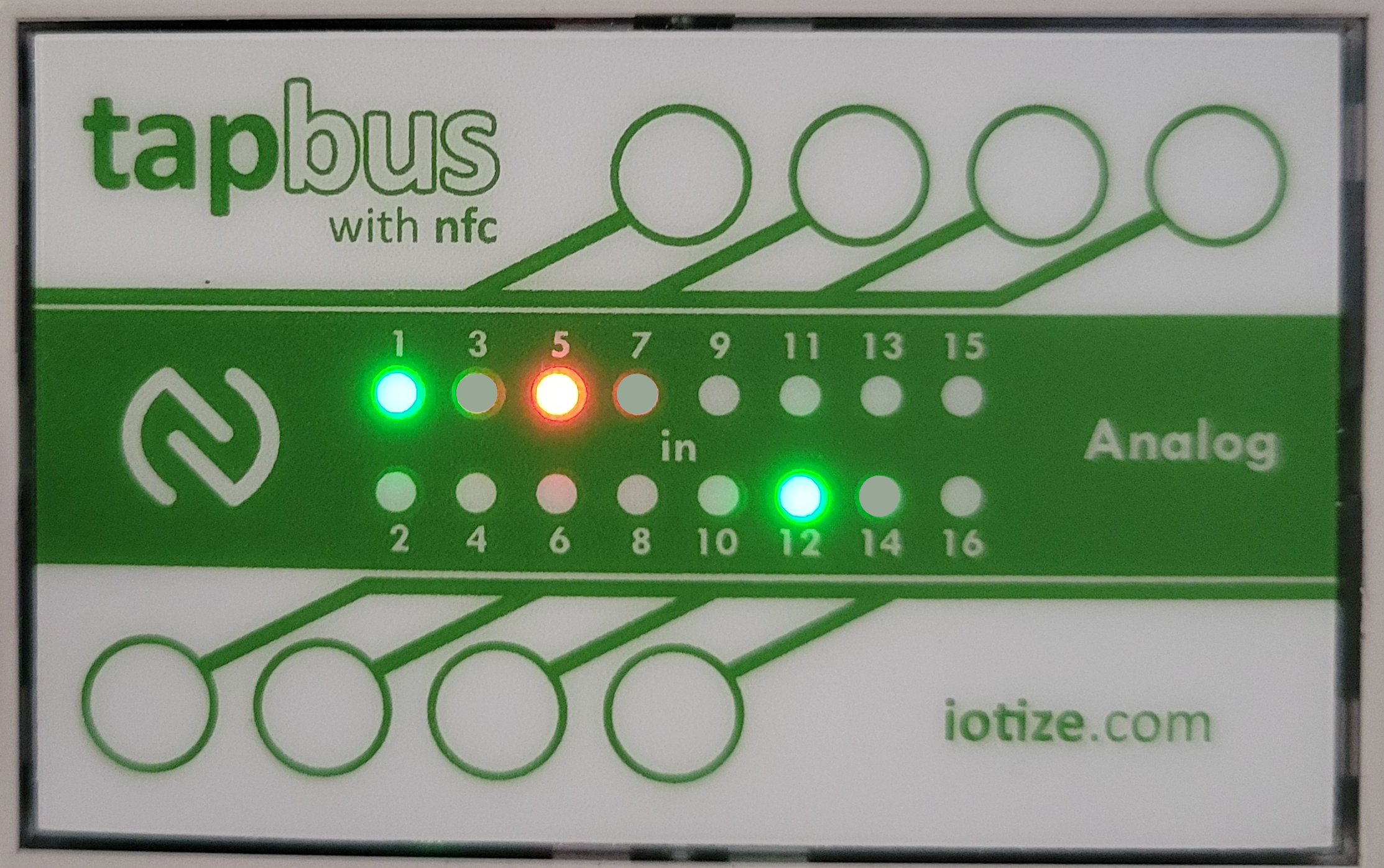
The NFC antenna is at the periphery of the panel.
The 16 LEDs represent the state of each channel. Their behaviour can be modified by Java, but by default:
-
a green LED means that it has been configured,
-
a red LED means that the channel presents an anomaly. Typically an out of range value for a 4-20 mA input, or for a resistor (open circuit or too high resistance value).
Channel Configuration
It is strongly recommended that you first configure from TapBus manager. Subsequently, configurations can be pre-programmed in order to short-circuit this step.
Input mode
It can be selected from the following:
| Mode | Description |
|---|---|
| Unused | Keep this when the channel is unused |
| 0-10V | For standard 0-10V sensors |
| 0-2V | Direct access (no division) to the ADC |
| 4-20mA | For standard 4-20mA sensors |
| Pt100-2 wires | Resistance measurement on 2 wires |
| Pt100-3 wires | Resistance measurement on 3 wires |
| Pt1000-2 wires | Resistance measurement on 2 wires |
| Pt1000-3 wires | Resistance measurement on 3 wires |
| Ohm-2W | Resistance measurement on 2 wires |
💡Note:
3 wires mode allows to discard the resistance of the wire. This mode is relevant for Pt100, but quite useless for Pt1000 (in this case, the resistance of the wires is negligible compared to that of the probe).
Low and High reference
The values to be considered for the lower and upper values in the range. Typically, when you have a pressure sensor with a 4-20mA, the lower value could be 0 bar (at 4mA) and 10 bar (at 20mA). If you enter 0-10, the output value will be automatically adapted (you will get 5 bar @ 12mA).
Store in datalog
Indicates that this specific channel has to be transmitted within a datalog message. Note that the you need to consider the high level settings to enable datalogging.
Extra Calibration
An additional calibration consists of applying an external value (known value). For example, you can connect a 100 ohm resistor to an input and then indicate that the value is exactly 100 ohms. The ratio between the "measured value" (may be 99.97) and the specified input (100) will be stored in the configuration (not in a file). Then the final result will take into account both ratio (first factory, then extra calibration).
When you change the configuration, the additional calibration will be lost, but the factory calibration will be retained (it is stored in a dedicated file).
Because the factory calibration is performed on all channels with an high end equipment, we do NOT recommend using the extra calibration feature.
Alarm settings
An alarm can be generated when a value is going out of the specified range. Note that the overall alarm mechanism has to be set properly.