Case of Modbus-RTU as master
The example below assumes the following configuration (which is probably the most common case):
-
Modbus-RTU over RS-485, with a Tapioca-RS-485
-
Tapioca plays the role of master, and external equipment plays the role of the slave.
Prerequisite
- We assume below that you own a Tapioca RS-485 (or TapNPass, TapBus,...).

-
A Modbus device (slave or master) running in RTU mode.
-
A cable to connect Tapioca to your Modbus device (RS232/RS485 Tapioca).
-
A mobile device with BLE and NFC connections enabled (the demo can work just using BLE, but it is more secure to use NFC for pairing).
-
A Windows based computer with IoTize Studio configuration software. Installation program is available on the Iotize Download section. If you need more information about Studio, see its manual on the here.
-
IoTize Tap Manager App (install from Google Play Store or from App Store), which is used:
-
to relay the configuration from IoTize Studio to Tapioca.
-
to run the Web monitoring app (static site), from its internal 'viewer'.
-
Connect cable between Tapioca and slave
Tapioca RS485 (or TapNPass) : use the RJ45 connector to connect your Tapioca to your device. If the RJ45 connector does not provide any power source, you need to provide it to the Tapioca through the power connector. Please refer to the datasheet for more detailled wiring information.
Create a new project
Launch IoTize Studio and create a new project using File|New which opens a Wizard from which you can enter:
- The Name of your project (for example 'test_modbus')
- The Location (folder) of the configuration file
- The Tap model: in this test_modbus demo, select your Tapioca model, which refines the choice of options in the following menus.
- A Modbus Dictionary: a CSV file that lists Modbus variables with their own parameters can be specified. At the moment, leave this field empty.

Once these fields are completed, tap the Create button.
Add registers
We will create a list of 'Modbus variables' that we will address in a specific way (and not by 'modbus direct'). The cleanest way is certainly to create a reference CSV file.
Create CSV Register Dictionary
To create your Register Dictionary, you can download our IoTize Modbus Register Dictionary generator:
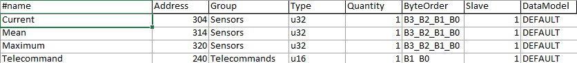
Open this spreadsheet and go to the Registers List tab. Here, enter the information for the Modbus variables of your target device:
| Property | Description | Possible Values | |||||||||||||||||||
|---|---|---|---|---|---|---|---|---|---|---|---|---|---|---|---|---|---|---|---|---|---|
| Name | The name that will be used by IoTize Studio to refer to the variable | String* | |||||||||||||||||||
| Address | The modbus address of the variable | Integer or Hexadecimal value example 0xF0 | |||||||||||||||||||
| Group | Name of the set the variable will be grouped in. This does not corresponds to any Modbus parameter, but helps to organize them in IoTize Studio, especially if there are lots of registers. | String* | |||||||||||||||||||
| Type | Data type of the variable. The first letter stands for signed s, unsigned u or float f, followed by the number of bytes. |
|
|||||||||||||||||||
| Quantity | Number of Type values to fetch. These will be given as an array of Type. | Integer | |||||||||||||||||||
| ByteOrder | This represents the endianness of the variable. Only for 16- and 32-bits types. |
|
|||||||||||||||||||
| Slave | The address of the slave that the variable refers to. | Integer | |||||||||||||||||||
| DataModel | Data model used by your Modbus implementation. If you don't know which is used, set it to Default**. |
|
This spreadsheet is configured to create a CSV file in a predefined format. DO NOT change its structure, otherwise IoTize Studio might not be able to read your Modbus Register Dictionary..
*The CSV uses commas or semi-colons as separators. String properties (Name and Group) must not contain these charaters.
**These values can be selected within a dropdown menu that appears when the cell is selected
Select the registers in Studio
Once your CSV file is added, open Iotize Studio. In the Resource view panel, select CSV and run the Add File command.

This command will import all the registers we defined into the CSV file:

You can then find the CSV registers and insert them into a bundle, either by Drag and Drop operation or by inserting them into the selected bundle by the Popup menu.

Note:
If you prefer not to create the CSV file, you can add registers directly in a bundle. In this case, you must indicate all the information relating to each register, as you will do in the CSV file.
Configure your project
Access control
In this project we have only one set with two registers which are both read-only registers. Thus, we will grant the anonymous profile access to these variables without restriction or the need for login.
Communication settings
Expand IOTZ Explorer (on the top left), select Target System sub menu and view the Target details window underneath the Explorer window.
The preset values depend on the previously opened project. You can overwrite and customize them to your target system:

-
Target protocol: Modbus /Serial standard
-
General Settings for communication (Modbus in this case): Slave Address, First register address, Baudrate, Parity, Length, Stop bits, Handshake and Timeout must be defined in accordance with your target system.
Configure your Tapioca
At this point, just go back to the previous tutorial: Gettings started with TapNLink
We can then:
-
Configure our Tapioca (the same way as you configure a TapNLink)
-
Perform initial tests in Studio,
-
Then create a dedicated mobile application.
To go further
You can find more information, with more varied examples, in the Manuals section.