Wireless Programming and Debugging for STM32 with TapNLink Primer
Introduction
Firmware can be updated and debugged using physical links such as USB, UART or I2C if there are specific physical connectors on the device. Physical access is not always possible, either because of the distance between the PC and the firmware or because the firmware is in a moving object.
TapNLink Primer provides the possibility to remotely update and debug firmware using a wireless BLE connection. In this tutorial we present the steps to use TapNLink Primer as an SWD programming and debugging tool in a Ride7 debugging environment. Programming via BLE is quite slow (about 3x slower than a connected debugger Raisonance's RLink), but the debugging speed is similar.
Prerequisites
Windows 10 PC
To use **TapNLink Primer** as a debugger you need a BLE enabled Windows 10 (version 1803 or above). If your PC does not have a BLE device integrated you can purchase a USB Bluetooth Dongle like CSR 4.0. Please verify that the dongle is compatible with Windows 10.TapNLink Primer Evaluation Kit
This kit allows iot designers to test all the advantages of **IoTize TapNLink** products for building a connected electronic system. For the purpose of this exercise, **TapNLink** is only used as an SWD debugging tool. You can purchase this kit from [Digikey](https://www.digikey.fr/en/product-highlight/i/iotize/tnl-primer-nb-tapnlink-primer-evaluation-kit).Ride7 + RKit ARM Software
Raisonance’s software toolset for ARM core-based microcontrollers is a fully integrated environment for building and debugging applications. **TapNLink Primer** can be used as a remote debugger for **Ride7** without any functional limitation (No license is needed). Download **Ride7 IDE** and **ARM RKit** (version &.70 or above) from [Raisonance Support website](http://support.raisonance.com/products-list).Step1: Hardware Preparation
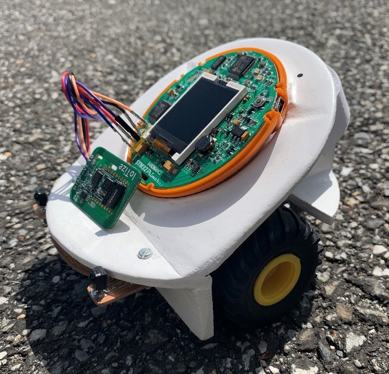
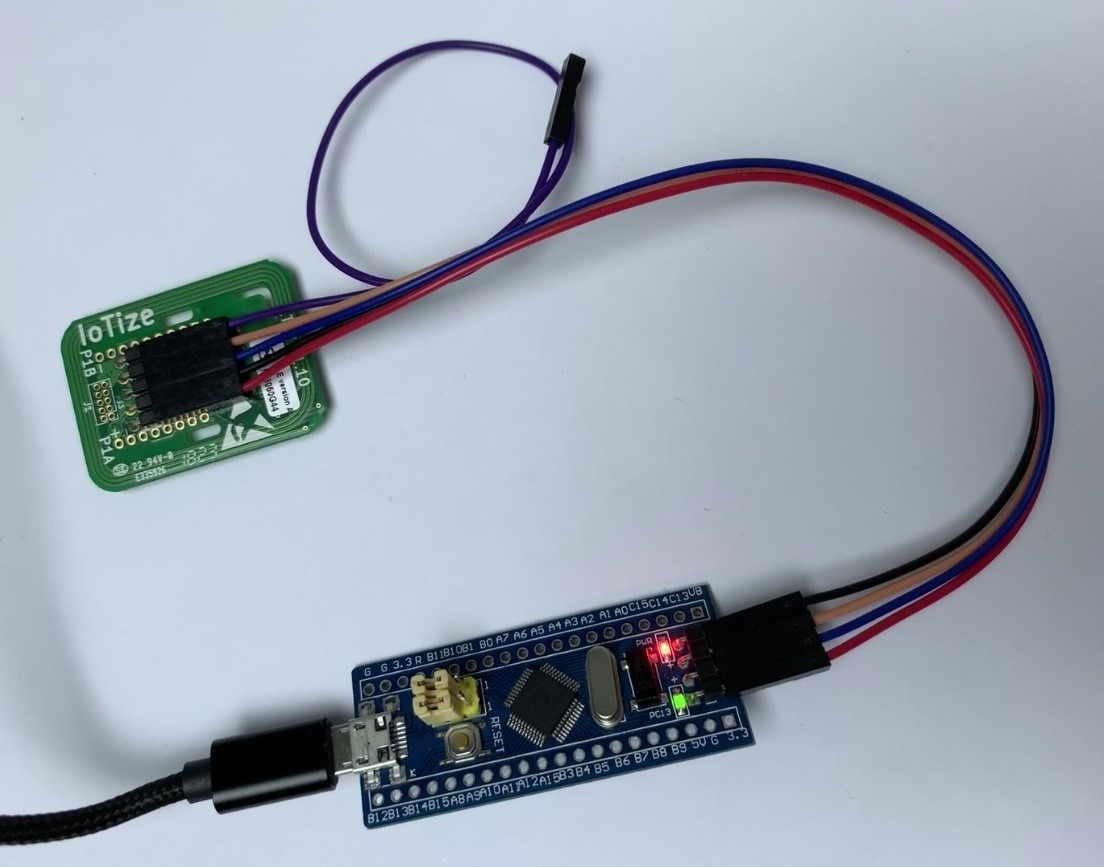
TapNLink Primer Evaluation Kit has the Sensor-demo sample application preloaded on an STM32F103x8 application board (Blue pill). Connect the STM32 application board to TapNLink as shown in this picture. Power the STM32 target board with a micro USB power cable: its red LED lights up and the green LED starts blinking. The target board powers the TapNLink Primer.
Step2: Ensure BLE peripherals are enabled
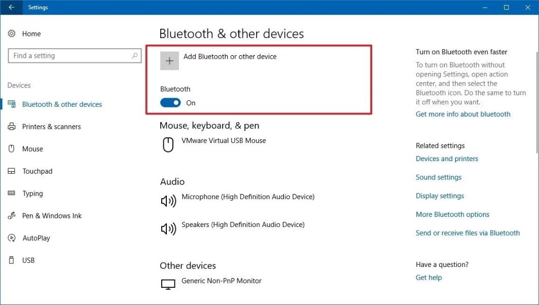
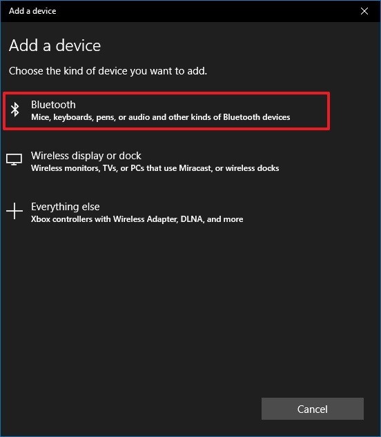
Open Windows10 Settings, click on Bluetooth & other devices. Turn on the Bluetooth toggle switch. Click the Add Bluetooth or other device button to explore the available BLE devices.
When scanning for Bluetooth devices that are available around your PC, you should find your TapNLink device displayed with the name of our sample application: Sensor demo_XXXXX, where XXXXX corresponds to the unique ID number associated with your TapNLink.
Step3: Install Ride7 development kit
Download and install Ride7 IDE, then RKit ARM from Raisonance Support Website.
RKit ARM has a set of application examples in the examples directory of Ride7 installation folder. Among these installed examples you will find the sensor_demo application example:
C:\Raisonance\Ride\Examples\ARM\Sensor_Demo\ STM32_Sensor.rprj
Double click the .rprj project file to open the project in Ride7 environment.
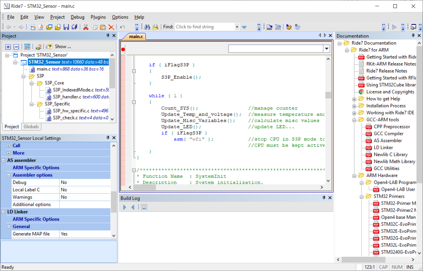
The STM32 Blue Pill board (included in the TapNLink Primer Evaluation Kit) is pre-programmed with this STM32_Sensor application. The application demonstrates a few simple features like blinking the board LED, measuring the internal temperature and voltage etc. In this exercise, we are going to build and debug this simple application using Ride7 development environment and TapNLink Primer as an SWD debugger.
Start by rebuilding the application using Project|Build Project command. Now you are ready to program and debug the application.
Step4: Setup your project to use TapNLink as the programming\debugging tool
From the STM32_Sensor Local settings pane, select TapNLink as the application’s debugging tool. Then scroll down the settings pane to reach the RLink configuration| Advanced Options:
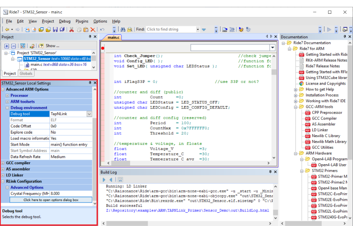
Click the 'Click here to open dialog box' button to configure TapNLink advanced options.
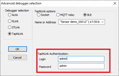
In the Advanced debugger selection dialog box, select TapNLink as the debugger tool, and BLE for the communication protocol. Programming and debugging are also available through Socket and MQTT relay but in this guide, we are going to focus on using BLE communication protocol. If you don’t know the advertised name of your TapNLink Primer device, you can click the button beside the Name or Address text field: Ride7 will scan and display the available devices, so you can find and select yours.
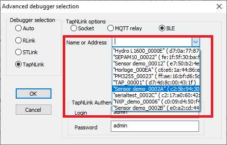
TapNLink connection to the target is protected with a User\Profile permission system. TapNLink Primers have a default administrator login configuration which Ride7 will use to access the target application.
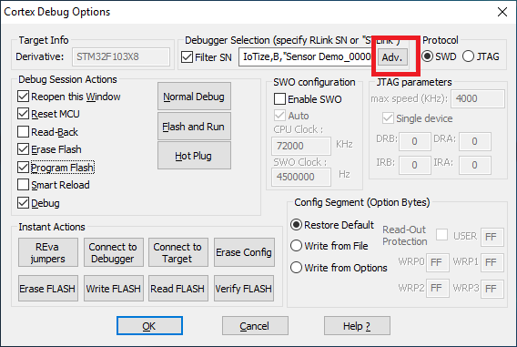
Select OK to close the dialog box. You are now ready to start programming your Blue Pill target board and debug the STM32_Sensor demo. Select Debug|Start command from the command bar and press ok to close the Cortex Debug Options dialog box.
Step5: Debugging STM32_sensor application
Ride7 is a fully integrated debugging environment with high-level language debugging features and a full range of views (Symbols, locals, disassembly, registers, peripherals, ...).

Troubleshooting
On Windows 10 1803 and above, your device may disconnect randomly resulting in connection fails and latency: Unpair the device from the BLE peripherals center of Windows 10 Settings and re-connect to your TapNLink device.
To go further
- Refer to Raisonance documentation to learn more about Raisonance’s ARM toolset and features.
- To learn more about IoTize TapNLink products, refer to IoTize documentation center.